Agilent Technologies B1500A Service Manual Page 57
- Page / 110
- Table of contents
- BOOKMARKS
- Agilent B1500A 1
- Semiconductor Device 1
- Analyzer 1
- Manual Part Number 2
- Warranty 2
- Technology Licenses 2
- Restricted Rights Legend 2
- In This Manual 4
- Class Exercises 6
- .xtr files 7
- Demo.xpg file 7
- .xtd files 7
- 1 ohm Resistor 10
- 1.1 kohm Resistor 10
- 511 kohm Resistor 10
- 0.1 uF Capacitor 10
- Module 1. Introduction 13
- Module 2. Getting Started 13
- Module 5. Basic Measurement 15
- Contents 20
- Contents-8 20
- 5 Basic Measurement 21
- In This Module 22
- SMU Block Diagram 23
- Basic Sweep Measurement 24
- Sweep Measurement Modes 25
- Combining VAR1, VAR1’, VAR2 25
- Why Four SMUs? 26
- Class Exercise 27
- SMU Triax Connection 28
- Wrong Triaxial Hookup 29
- Jumper Leads – MOS transistor 30
- To Import Demo Data 31
- To Get Setup Data 32
- Classic Test – Channel Setup 33
- Do not abort on 34
- Classic Test – Display Setup 35
- To Start Measurement 36
- Data Display Window – Graph 37
- Data Display Window - List 38
- Paste to Notepad 39
- To Copy List Data 39
- Application Test 40
- Module 5 41
- Basic Measurement 41
- SMUs May Be Connected 42
- 200 V Resistor Sweep 43
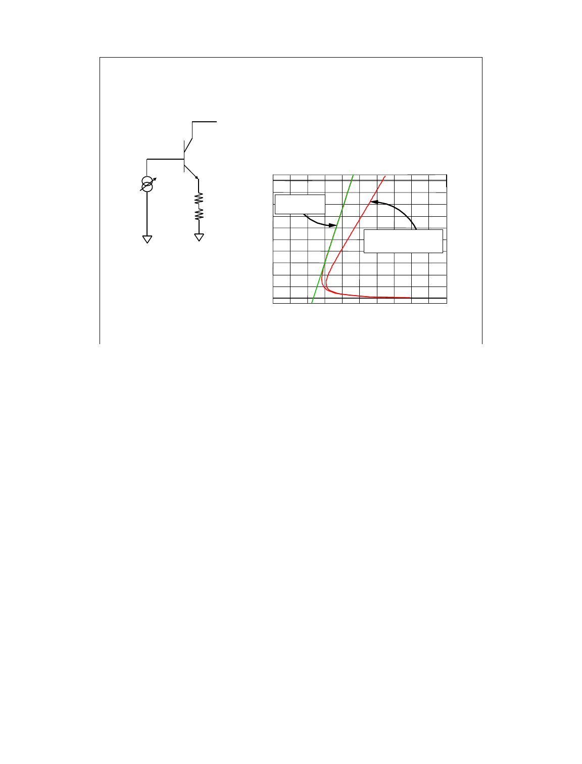
- 200 V BVceo 43
- Two SMUs in Series 44
- Voltage across resistor 44
- VR = V1-V2 44
- VAR1' Ratio = -1 45
- Measurement and Display Pages 45
- Graphics Page 0 to 200 V 46
- 200 mA Output 47
- Two SMUs in Parallel 48
- Current in resistor 48
- Itotal = I1+I2 48
- VAR1' Ratio = 1 49
- Resistor 50
- Graphics Page 0 to 200 mA 50
- Cabling and Fixturing Issues 51
- Simplified Diagram 52
- Kelvin Triaxial Cable 56
- Why Kelvin Measurements? 57
- Cable Connections 59
- Class Example - Jumper Leads 60
- 2. Click Recall button 61
- To Get REKELV Test Setup: 61
- Single Kelvin Measurement 62
- Non-Kelvin Measurement 63
- To Kelvin Probe 64
- To Guarded Chuck 64
- Connector Plate 65
- Guarded to within 2mm of tip 67
- Single Triax Kelvin Triax 67
- Triaxial Probes 67
- Simplifying RF Connections 68
- Interlock Connection 69
- 16493J-001 1.5 m cable 70
- 16493J-002 3.0 m cable 70
- 16442A/B Fixture 70
- 16058A Fixture Compatibility 71
- 6 Low Current Measurement 73
- Low Current Measurement 75
- What is possible? 75
- Challenges 76
- Clean Probing Environment 77
- What is Required? 77
- Where to Start? 78
- Low Current 79
- Calibration & Zero Cancel 79
- Calibration 80
- Measurements Near Zero fA 81
- ZERO CHECK - No cable 82
- Using Default SMU Setup 82
- Delete SMU1 and SMU2 83
- Change Mode to V and 83
- Function to VAR1 83
- ZERO CHECK 83
- Channel Setup 83
- Do not change this screen 84
- Display Setup 86
- Bumping cable 88
- Bending Cable 88
- Effect of cable movement 88
- Appendix: Using ASU 89
- Configuration 90
- HRSMU+ASU 91
- Low Current Subthreshold 92
- SD214DE MOS Subthreshold 94
- Trade Off Speed vs Accuracy 95
- What is measured? 96
- Low Current Gummel Plot 97
- Module 6 98
- Small step size 99
- Negative sweep values 99
- Range and Integration Time 100
- Maximum resolution 100
- Gummel Plot 100
- LOW CURRENT MEASUREMENT 101
- Gummel Plot With 102
- ULTRA LOW CURRENT 103
- Subthreshold Curve 103
- Small STEP: 100 mV 104
- Large HOLD TIME: 3 sec 104
- Measurement Setup 104
- Set long integration time 106
- Leakage to fA levels 107
- Chuck must be guarded 107
- Fowler-Nordheim (FN) Plot 108
- Negative sweep 109
- Accumulation mode 109
- Wait for 5 V initial step 109
- FOWLER-NORDHEIM PLOT 109
- Measurement Page 109
- Low Current Gate Oxide Meas 110
- Using Guarded Chuck 110
Related products and manuals for Measuring, testing & control Agilent Technologies B1500A
 (628 pages)
© 2020, manymanuals.com. All rights reserved. | 0.793 s |
 Manymanuals.com
 Manymanuals.de
 Manymanuals.fr
 Manymanuals.it
 Manymanuals.pl
 Manymanuals.cz
 Manymanuals.es
 Manymanuals-pt.com
Comments to this Manuals