Agilent Technologies 4294A Specifications Page 87
- Page / 126
- Table of contents
- BOOKMARKS
- Agilent Technologies 1
- Impedance Measurement 1
- Handbook 1
- SECTION 1 7
- Impedance measurement basics 7
- 1-2. Measuring impedance 9
- SECTION 2 15
- I-V method 16
- RF I-V method 16
- Network analysis method 16
- Auto balancing bridge method 17
- SECTION 3 37
- Fixturing and cabling 37
- 3-3. Test fixtures 41
- 3-4. Test cables 44
- Figure 3-9. 4TP-4TP extension 46
- 3-7. RF test fixtures 49
- SECTION 4 53
- SECTION 5 75
- Table 5-1. Capacitor types 76
- 5-2. Inductor measurement 79
- 5-3. Transformer measurement 83
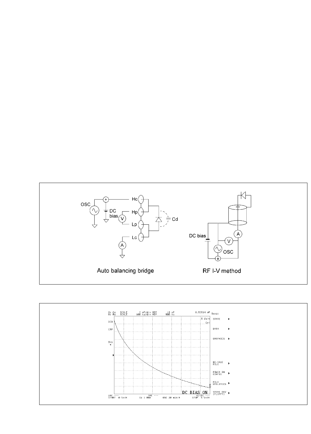
- 5-4. Diode measurement 87
- 5-5. MOS FET measurement 88
- Agilent 4294A 91
- 42941A Impedance Probe 91
- Figure. 5-28 93
- 5-8. Resonator measurement 94
- 5-9. Cable measurements 97
- 5-11. Battery measurement 101
- APPENDIX A 113
- Type of error Impedance 117
- APPENDIX B 119
- Open and short compensation 119
- APPENDIX C 121
- APPENDIX D 123
- APPENDIX E 125
- Agilent Email Updates 126
- Agilent Direct 126
Related products and manuals for Multimeters Agilent Technologies 4294A
 (21 pages)
© 2020, manymanuals.com. All rights reserved. | 1.050 s |
 Manymanuals.com
 Manymanuals.de
 Manymanuals.fr
 Manymanuals.it
 Manymanuals.pl
 Manymanuals.cz
 Manymanuals.es
 Manymanuals-pt.com
Comments to this Manuals